Page 1 of 1
Why Solidworks prevents adding this hole?
Posted: Tue Jan 17, 2023 2:33 am
by Tera
-
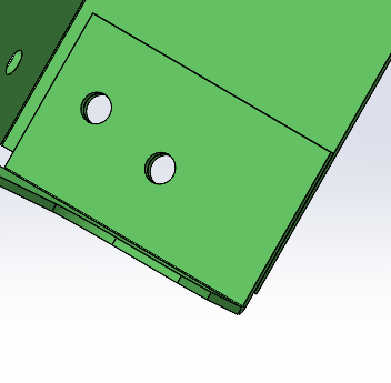
This is a very simple sheet metal part. I have a Ø6.0mm hole added with hole wizard. When I edit hole's sketch (Sketch49) and add a point (near in blue circle), Solidworks keeps giving me Zero Thickness error and denies to add the hole.
How adding a hole to an existing hole may cause zero thickness geometry?
Thanks.
Re: Why Solidworks prevents adding this hole?
Posted: Tue Jan 17, 2023 6:42 am
by DennisD
Tera wrote: ↑Tue Jan 17, 2023 2:33 am
33.png
-
This is a very simple sheet metal part. I have a Ø6.0mm hole added with hole wizard. When I edit hole's sketch (Sketch49) and add a point (near in blue circle), Solidworks keeps giving me Zero Thickness error and denies to add the hole.
How adding a hole to an existing hole may cause zero thickness geometry?
Thanks.
We can only speculate from the information you provided. Post the part and I am sure you will get a helpful answer quickly.
Re: Why Solidworks prevents adding this hole?
Posted: Tue Jan 17, 2023 7:06 pm
by Tera
Sorry, I thought I have had attached the part. Seems that I've forgotten.
My apologies. It's added to the first post above now.
Re: Why Solidworks prevents adding this hole?
Posted: Tue Jan 17, 2023 7:54 pm
by SPerman
I had it fail on me once, but was never able to repeat it. I've moved the hole around to several positions since then and it is happy.
- image.png (20.15 KiB) Viewed 4245 times
Re: Why Solidworks prevents adding this hole?
Posted: Tue Jan 17, 2023 8:18 pm
by Tera
@SPerman Seems it's your lucky day. You may want to buy lottory.
No matter how many times I try, I can't add new holes.
Can you test this please?
Delete the existing hole. Can you add new holes?
Thank you.
Re: Why Solidworks prevents adding this hole?
Posted: Tue Jan 17, 2023 8:34 pm
by Tera
I'm not even able to add a hole to the outside plate that goes through both plates.
-
Re: Why Solidworks prevents adding this hole?
Posted: Wed Jan 18, 2023 3:21 am
by acmall
When I do a forced rebuild on your part after opening it I get an error on Flange W that the part intersects itself. Appears to be related to the two flanges not having any clearance (1.6mm material & 1.6mm offset). If I increase the offset to 1.61 the error goes away and I can create holes through the flanges.
Re: Why Solidworks prevents adding this hole?
Posted: Wed Jan 18, 2023 5:52 am
by gupta9665
Same results as @acmall i.e. the flange seems to be giving issue. And on changing the offset to 1.61, the issue is fixed.
Re: Why Solidworks prevents adding this hole?
Posted: Wed Jan 18, 2023 5:59 am
by Tera
acmall wrote: ↑Wed Jan 18, 2023 3:21 am
When I do a forced rebuild on your part after opening it I get an error on Flange W that the part intersects itself. Appears to be related to the two flanges not having any clearance (1.6mm material & 1.6mm offset). If I increase the offset to 1.61 the error goes away and I can create holes through the flanges.
Solidworks Sucks in sheet metal. They know it and that's why they have an option to bypass the error you mentioned.
0 clearance is different with intersect. We are manufacturing several thousands of these kind of brackets and it's absolutely possible. If we have a clearance between two flanges, how can we spot weld them?
Moreover,
@SPerman was able to add the holes without adding a gap between two flanges.
I have had these kind of bends in previous versions and never have seen this. Maybe something have changed in 2022.
Million thanks for taking your time and looking into this.
Re: Why Solidworks prevents adding this hole?
Posted: Wed Jan 18, 2023 6:09 am
by Tera
gupta9665 wrote: ↑Wed Jan 18, 2023 5:52 am
Same results as @acmall i.e. the flange seems to be giving issue. And on changing the offset to 1.61, the issue is fixed.
Can you tell, why I have a hole and nothing's wrong. And only the second hole throws this error?
Having no gap between two flange isn't different with zero thickness geometry?
If I have two extrude one over the other and don't merge them, SW doesn't give me that error.
Thank you.
Re: Why Solidworks prevents adding this hole?
Posted: Wed Jan 18, 2023 8:08 am
by SPerman
I am using 2022 SP5.
I created a section view, so I could look normal to the face, to better understand where I was placing holes.
I can get it to fail under 2 conditions.
1: If the holes breaks through the edge of either the top or bottom flange.
2: If the holes overlap.
Otherwise, I cannot get it to fail. My best guess is that the 2nd hole you are placing breaks an edge, but it is difficult to tell if you are looking on an angle.
I am GIF. Click Me!
Re: Why Solidworks prevents adding this hole?
Posted: Wed Jan 18, 2023 8:43 am
by Tera
SPerman wrote: ↑Wed Jan 18, 2023 8:08 am
Otherwise, I cannot get it to fail. My best guess is that the 2nd hole you are placing breaks an edge, but it is difficult to tell if you are looking on an angle.
Obviously my point is not on the edge.
Can you check the attached file too? This is what I have of the attached file.
-
-
Thanks again.
Re: Why Solidworks prevents adding this hole?
Posted: Wed Jan 18, 2023 9:00 am
by josh
Tera wrote: ↑Wed Jan 18, 2023 5:59 am
Solidworks Sucks in sheet metal. They know it and that's why they have an option to bypass the error you mentioned.
0 clearance is different with intersect. We are manufacturing several thousands of these kind of brackets and it's absolutely possible. If we have a clearance between two flanges, how can we spot weld them?
Moreover, @SPerman was able to add the holes without adding a gap between two flanges.
I have had these kind of bends in previous versions and never have seen this. Maybe something have changed in 2022.
Million thanks for taking your time and looking into this.
Whether or not you get errors probably depends on this setting:
Solidworks sucks at zero thickness geometry. This is a limitation of the Parasolid kernel that SW is built on. As you mentioned, there's an option to ignore self-intersection in sheet metal features. And as you've discovered, it's probably a bad idea to use it. You can get your flanages to build, but intentionally creating an invalid body and then continuing to perform operations on it is asking for trouble.
Of course you can physically manufacture them. There's a lot you can do in CAD that you can't do in metal and vice versa. However... If were wanting to talk about the differences between CAD and real life, there's some amount of clearance in there somewhere. In fact, especially after you spot weld, I'm pretty sure every bit of that overlap has clearance except for the actual positions of the welds.
There's no reason for us to keep checking your files. You're modeling them using poor practices, failing to account for the limitations of the tool you're using. There are a lot of things SW will
let you do that you probably
shouldn't do if you can at all help it.
Re: Why Solidworks prevents adding this hole?
Posted: Wed Jan 18, 2023 9:46 am
by Frederick_Law
Which CAD you used allow 2 features with 0 distance?
SW and IV won't allow that.
SW will have ZTG error.
IV will combine the face and it won't flatten.
Best practice is make a small gap, 0.001" or 0.0001".
Re: Why Solidworks prevents adding this hole?
Posted: Wed Jan 18, 2023 9:57 am
by jcapriotti
josh wrote: ↑Wed Jan 18, 2023 9:00 am
Of course you can physically manufacture them. There's a lot you can do in CAD that you can't do in metal and vice versa. However... If were wanting to talk about the differences between CAD and real life, there's some amount of clearance in there somewhere. In fact, especially after you spot weld, I'm pretty sure every bit of that overlap has clearance except for the actual positions of the welds.
Ok guys, I'm going to argue that you aren't actually manufacturing a perfect 0 gap part. There is a gap, it's small but its there. You can put a 0.001" gap between the flanges and the issue goes away. I know if seems you shouldn't have to but...well...SolidWorks. Someone mentioned parasolid as the culprit....does Solid Edge have this issue?
Re: Why Solidworks prevents adding this hole?
Posted: Wed Jan 18, 2023 10:00 am
by zxys001
Frederick_Law wrote: ↑Wed Jan 18, 2023 9:46 am
Best practice is make a small gap, 0.001".
...want a T-Shirt with that printed!

Re: Why Solidworks prevents adding this hole?
Posted: Wed Jan 18, 2023 10:02 am
by Frederick_Law
jcapriotti wrote: ↑Wed Jan 18, 2023 9:57 am
Someone mentioned parasolid as the culprit....does Solid Edge have this issue?
Even AutoCAD will combine the feature if they're "touching" or zero distance.
Unless they're different bodies.
Re: Why Solidworks prevents adding this hole?
Posted: Wed Jan 18, 2023 10:04 am
by Frederick_Law
zxys001 wrote: ↑Wed Jan 18, 2023 10:00 am
...want a T-Shirt with that printed!
0.0001" better. Dimension will looks "correct" on 3 decimal.
Re: Why Solidworks prevents adding this hole?
Posted: Wed Jan 18, 2023 10:05 am
by bnemec
josh wrote: ↑Wed Jan 18, 2023 9:00 am
Whether or not you get errors probably depends on this setting:
image.png
Solidworks sucks at zero thickness geometry. This is a limitation of the Parasolid kernel that SW is built on. As you mentioned, there's an option to ignore self-intersection in sheet metal features. And as you've discovered, it's probably a bad idea to use it. You can get your flanages to build, but intentionally creating an invalid body and then continuing to perform operations on it is asking for trouble.
Of course you can physically manufacture them. There's a lot you can do in CAD that you can't do in metal and vice versa. However... If were wanting to talk about the differences between CAD and real life, there's some amount of clearance in there somewhere. In fact, especially after you spot weld, I'm pretty sure every bit of that overlap has clearance except for the actual positions of the welds.
There's no reason for us to keep checking your files. You're modeling them using poor practices, failing to account for the limitations of the tool you're using. There are a lot of things SW will
let you do that you probably
shouldn't do if you can at all help it.
I cannot open the attached file, but not sure what the poor practices is all about. From the info in this thread there's a lapped corner with the flanges being tight together and then add a hole feature through them or am I missing something? I just did that in Solid Edge (parasolid) and I cannot get it to fail. I agree that trying repeatedly to do things that the CAD system doesn't support is bad practice. But how does one know all the things a CAD system cannot do? I assume by trying and failing or by guidance of others. They sure as heck don't cover all these pitfalls in the training!
Re: Why Solidworks prevents adding this hole?
Posted: Wed Jan 18, 2023 10:08 am
by Frederick_Law
bnemec wrote: ↑Wed Jan 18, 2023 10:05 am
I just did that in Solid Edge (parasolid) and I cannot get it to fail.
Can you get flat pattern?
Measure with all decimal and see if it's 0.
Maybe SE found a way to cheat ZTG.
Re: Why Solidworks prevents adding this hole?
Posted: Wed Jan 18, 2023 10:15 am
by bnemec
Frederick_Law wrote: ↑Wed Jan 18, 2023 10:08 am
Can you get flat pattern?
Nothing special for that. I'd guess we had dozens if not hundreds of files in our data set like this. Out of ~40k+ .psm files.
Now, there may have been times where downstream features that interacted with these flanges may have gotten flaky and I'll agree it could have been due to the no-gap between the flanges. I just cannot think of any scenarios off the top of my head to try out.
Re: Why Solidworks prevents adding this hole?
Posted: Wed Jan 18, 2023 10:27 am
by bnemec
Frederick_Law wrote: ↑Wed Jan 18, 2023 10:08 am
Can you get flat pattern?
Measure with all decimal and see if it's 0.
Maybe SE found a way to cheat ZTG.
Took me a bit to remember how to go in to change the default precision. I think you are correct that there is a gap; maybe 0.0004". I'm checking to see if SE does that automatically or just dumb luck on my part. I just made the flanges and selected the default flange position that would make them tight.
From what I can see Solid Edge takes the liberty to offset the face that the flange comes off of by 0.0004" so that the lapped flange has a gap. The inside radius and flange thickness are still nominal. I was able to put a manual offset in the flange = 0.0004" and Solid Edge then fired off the ZTG error.
There is no way to deal with the ZTG, just guide the user away from it.
Re: Why Solidworks prevents adding this hole?
Posted: Wed Jan 18, 2023 11:13 am
by jcapriotti
zxys001 wrote: ↑Wed Jan 18, 2023 10:00 am
...want a T-Shirt with that printed!
Or how about......
Re: Why Solidworks prevents adding this hole?
Posted: Wed Jan 18, 2023 11:30 am
by jcapriotti
@Tera You can add the gap to your equations.....
Re: Why Solidworks prevents adding this hole?
Posted: Wed Jan 18, 2023 2:35 pm
by JSculley
bnemec wrote: ↑Wed Jan 18, 2023 10:05 am
I cannot open the attached file, but not sure what the poor practices is all about. From the info in this thread there's a lapped corner with the flanges being tight together and then add a hole feature through them or am I missing something? I just did that in Solid Edge (parasolid) and I cannot get it to fail.
SOLIDWORKS can do this just as well. Something is out of whack in the original model, but recreating it in SW2022 I didn't have a problem:
There's no gap:
Re: Why Solidworks prevents adding this hole?
Posted: Wed Jan 18, 2023 6:18 pm
by Tera
JSculley wrote: ↑Wed Jan 18, 2023 2:35 pm
SOLIDWORKS can do this just as well. Something is out of whack in the original model, but recreating it in SW2022 I didn't have a problem:
I recreate the part to see how it goes on me.
Thank you.