Page 1 of 1
GD&T
Posted: Fri Jun 16, 2023 3:05 pm
by Frederick_Law
Something to think about on the weekend:
The intend is to make the holes line up on both flange.
Yes, adding locational on the holes will do but it means nothing for brake operator. Said the boss.
So we want both flange to be parallel and length (2.120) within 0.01 from each other.
2.120 is not critical as long as both flanges are "equal".
If one flange is 2.1, the other should be 2.1 +/- 0.01.
I still don't think it'll "fix" hole alignment problem.
We don't want to build jig to check. 3 similar parts, 3 different length each.
Re: GD&T
Posted: Fri Jun 16, 2023 3:46 pm
by AlexB
This still depends on the global tolerance. If you have ±.030" then your flanges can be 2.150" and 2.090" but still be parallel to one another within .010".
The ASME Y14.5 Standard has this to say about co-planar features
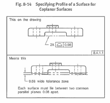
- image.png (47.22 KiB) Viewed 5608 times
With that said, if you add this requirement, I still don't think this solves the issue because:
- The holes are dimensioned from the base of the plate, not the bottom edge of the bent flange. The GD&T would have to be a 'Position' tolerance for these on either side.
- I know our sheet metal guys would push back on tolerances of less than ±0.030" across a bend. However, your capabilities may differ.
Edit: your boss will probably say this means nothing to the brake operator as well, to which I would respond that the brake operator needs updated training.
Re: GD&T
Posted: Sun Jun 18, 2023 8:14 pm
by zwei
Frederick_Law wrote: ↑Fri Jun 16, 2023 3:05 pm
Yes, adding locational on the holes will do but it means nothing for brake operator. Said the boss.
Why does it means nothing for brake operator?
Re: GD&T
Posted: Mon Jun 19, 2023 8:43 am
by Frederick_Law
Brake care only 2.120 flange length. That's what they can work with. Hole location doesn't.
Technically holes should be in correct location after punch.
In reality a jig to check if pins go through all 4 holes would be perfect.
But we don't live in a perfect world.
In reality we need better brake operator .....
Re: GD&T
Posted: Mon Jun 19, 2023 4:03 pm
by jcapriotti
What's more important, the flange length or the hole alignment?
Re: GD&T
Posted: Mon Jun 19, 2023 4:28 pm
by SamSpade
We come across this situation often enough, and I believe the way you've shown it should suffice. We also add a note requiring that the holes in both flanges be concentric with the required tolerance.
Re: GD&T
Posted: Tue Jun 20, 2023 9:43 am
by Frederick_Law
jcapriotti wrote: ↑Mon Jun 19, 2023 4:03 pm
What's more important, the flange length or the hole alignment?
Hole alignment.
If part is punched correctly and flanges are bend correctly, holes should line up.
In theory, yes.
And measure flange length is easier for brake operator. We "believe".
I keep telling them if faith and believe is what they want, walk down the street. There is a church there.
Re: GD&T
Posted: Tue Jun 20, 2023 10:04 am
by bnemec
We work with the exact same situations. Boiled down, the intent of drawing is to communicate. Engineer/Designer are trying to communicate a bunch of things; design intent, significant characteristics, what the object needs to be. The design drawing does not define how it is to be made. When we purchase a part the vendor always makes their own drawing for their own needs, even when we own the design. The drawing is laid out in a way that defines how it is made according to their certainty in their processes. Yet when we make a part ourselves we try to manufacture off the design print, the print that says what it is not how it's made. Two different purposes should have two different documents. The two drawings may then use the language (GD&T for example) that is most appropriate for communicating the content to the intended recipient. Typically speaking GD&T to machine operators is not helpful, if they are fluent in GD&T then I would be trying to get them into a different job, like making mfg drawings for me.
Re: GD&T
Posted: Tue Jun 20, 2023 10:14 am
by jcapriotti
Frederick_Law wrote: ↑Tue Jun 20, 2023 9:43 am
Hole alignment.
If part is punched correctly and flanges are bend correctly, holes should line up.
In theory, yes.
And measure flange length is easier for brake operator. We "believe".
True, the brake operator is really concerned with flange length..........but the design can dictate the manufacturing method depending on what is really important. If the hole alignment is most important, it may make sense to manufacture the part differently. You may create a die/mold to form the part, or drill the holes after forming. There are CNC automated sheet metal forming equipment that is more precise, but if you are using press brakes with manual operators, it tends to be less accurate.
We had a similar requirement with a "hat" shaped sheet metal part that needed holes aligned across the part. We ended up outsourcing the part since our equipment and operators couldn't form it accurately enough on a consistent basis.
Re: GD&T
Posted: Tue Jun 20, 2023 11:51 am
by Frederick_Law
bnemec wrote: ↑Tue Jun 20, 2023 10:04 am
Two different purposes should have two different documents. The two drawings may then use the language (GD&T for example) that is most appropriate for communicating the content to the intended recipient. Typically speaking GD&T to machine operators is not helpful, if they are fluent in GD&T then I would be trying to get them into a different job, like making mfg drawings for me.
True.
This boil down to how to put on the drawing:
Bend both flanges within 0.010" of each other.
Keep 2.000 within tolerance.
Of course we got parts failed because the back stop was tilted and the flanges were not parallel but still within tolerance.
So we try to update the drawing with enough tolerance to get the right part.
A good thinking exercise on GD&T.
Re: GD&T
Posted: Tue Jun 20, 2023 2:34 pm
by bnemec
Frederick_Law wrote: ↑Tue Jun 20, 2023 11:51 am
True.
This boil down to how to put on the drawing:
Bend both flanges within 0.010" of each other.
Keep 2.000 within tolerance.
Of course we got parts failed because the back stop was tilted and the flanges were not parallel but still within tolerance.
So we try to update the drawing with enough tolerance to get the right part.
A good thinking exercise on GD&T.
That's my lay understanding of GD&T premise. Instead of needing to hold both bend locations to 0.010 and angles to 0.5 deg to get the holes to be lined up we can accept a much larger manufacturing variance in the features that don't matter as long as those holes are lined up. GD&T can do that in one callout and let everything else be +-0.060 if you want.
But as many stated, GD&T doesn't help operators set up the machine or load it correctly.
Re: GD&T
Posted: Tue Jun 20, 2023 5:30 pm
by jcapriotti
bnemec wrote: ↑Tue Jun 20, 2023 2:34 pm
But as many stated, GD&T doesn't help operators set up the machine or load it correctly.
It's like to reading ancient Greek to most people. To take your old quote and rework it "There are two kinds of engineers, those that don't know GD&T, and those that think they know GD&T.
Re: GD&T
Posted: Wed Jun 21, 2023 4:48 pm
by MattW
I know I am preaching to the choir here, but you say that hole alignment matters but it isn't called out at all. It sounds like you are attempting a manufacturing document and hoping that controlling the edge of one flange relative to the other will get you you the results you want, which it might. In that case your second drawing would be the approach I would use, although you should use position and not parallelism. Although it sounds like you are working with staff who are incapable of inspecting to a drawing this complicated. (I don't think it is complicated).
It also sounds like you have spent more time and money trying to work around your problems than if you just had a drawing that asked for what you want and built an inspection jig to verify the part, which could be very simple in this case.
Re: GD&T
Posted: Thu Jun 22, 2023 8:45 am
by Frederick_Law
MattW wrote: ↑Wed Jun 21, 2023 4:48 pm
It also sounds like you have spent more time and money trying to work around your problems than if you just had a drawing that asked for what you want and built an inspection jig to verify the part, which could be very simple in this case.
I need you to come and explain that to management

Re: GD&T
Posted: Thu Jun 22, 2023 9:10 am
by Frederick_Law
This is what's in the shop now:
I don't think it relay the intent completely.
Re: GD&T
Posted: Thu Jun 22, 2023 1:45 pm
by MattW
I think your drawing is getting worse, but it sounds like you are doing what your are told.
A jig like this would verify alignment and hole minimum size and represent probably less than an hours worth of work. There might be good reasons to not do this.
Re: GD&T
Posted: Thu Jun 22, 2023 4:23 pm
by Frederick_Law
That drawing was approved by management and QC. I tried but they believe they're correct.
A jig need to be "certified". Check on CMM.
Technically not complicated.
5 measurements. One at each end of the flange (2.12). All 4 should be within 0.01. 2.12 ref only.
And 2.000 +0.020 -0.
Re: GD&T
Posted: Sun Jun 25, 2023 5:35 pm
by jcapriotti
@Frederick_Law The drawing does little to insure the holes are aligned across both flanges. There is a lot of room for tolerance stack up with the dimensions and standard ± tolerancing. I don't know the design intent so its hard to say for sure, but the holes need to be toleranced relative to each other with a position tolerance, not the edges so much.
This is likely overkill for your equipment's capabilities, and I just made up some numbers. Ultimately, you have a design requirement and the drawing needs to reflect that. Your manufacturing can either meeting the requirement or not, then you negotiate.
My GD&T-fu is rusty....but here goes....
Gage to check based on
@MattW suggestion.