Page 1 of 1
"Folding" a sketch over an edge
Posted: Mon Jul 31, 2023 11:12 pm
by Harry Sig
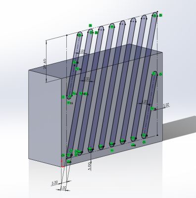
Hey everyone. I'm relatively new to CAD so I do not know the in's and out's of Solidworks yet. For the last 30 minutes or so, I've been trying to "fold" a sketch over a 90 degree edge to make a somewhat complex (for me) extrude cut over two faces. The only google search results I've seen relates to sheet metal and sketched bends, but to my knowledge you can only make a curved bend rather than a sharp edge. Is there any way to accomplish what I have been try to do?
Re: "Folding" a sketch over an edge
Posted: Tue Aug 01, 2023 10:05 am
by matt
If I understand you correctly, you would get the part into a flattened state, and then cut it there, same as the manufacturing process. You can cut with 3D sketches, but that's more complex than it needs to be.
If you need something more specific, post a model or make a visual of what you're trying to create.
If you're trying to cut the block with the angled flat pieces, if you just cut the 3d part, the cut will make the correct cuts all the way around, you don't have to do that manually.
Re: "Folding" a sketch over an edge
Posted: Tue Aug 01, 2023 5:20 pm
by bnemec
Is this going to be a sheet metal part or machined?
Re: "Folding" a sketch over an edge
Posted: Tue Aug 01, 2023 6:03 pm
by Harry Sig
bnemec wrote: ↑Tue Aug 01, 2023 5:20 pm
Is this going to be a sheet metal part or machined?
Neither actually. I'm just a high school senior that only has access to 3D printers. The part in question is just a case to hold my raspberry pi and a couple single-board cameras. The slots shown in the original post were supposed act as air vents across two adjacent surfaces to disperse the pi's heat (I may be overestimating how hot pi's get). Even if they did not function as so, I still think it would be cool to take a peek inside. I did some work on the part after the first post and now it looks like this without the air vents:
Re: "Folding" a sketch over an edge
Posted: Tue Aug 01, 2023 6:40 pm
by matt
Just make the cut from the sketch you show in the first images you posted, and use the depth of cut to determine how far down the side the cut goes.
The sides of the cut will be angled, but since you're 3D printing, just put fillets on it and it won't matter.
Re: "Folding" a sketch over an edge
Posted: Tue Aug 01, 2023 6:57 pm
by Dennis Bacon
I'm thinking you would like to use the wrap command for this.
Re: "Folding" a sketch over an edge
Posted: Tue Aug 01, 2023 7:49 pm
by zwei
Not sure will this help...
but for case like this where i know the "bend line" i often just create a dummy surface and create split line on the dummy surface using the sketch
After that i just rotate it around and project it accordingly...
Or like other mentioned, you could use wrap feature (although i find wrap does not work that well for more complex surface)
Re: "Folding" a sketch over an edge
Posted: Tue Aug 01, 2023 9:04 pm
by SPerman
Another, less elegant solution would be to create a sketch block with a reference line representing the edge of the box. You would then use this sketch block to drive two cuts on two faces. But I would use wrap.
Re: "Folding" a sketch over an edge
Posted: Tue Aug 01, 2023 9:05 pm
by Harry Sig
Thank you everyone for responding, I found Dennis Bacon's wrap solution works the best for the situation. I was unaware the wrap feature could be used on any face. I previously thought it was reserved for cylindrical surfaces only. Although the edges are a little strange, I am almost certain I wont be able to notice once its printed due to its small size. Here is the final part:
Re: "Folding" a sketch over an edge
Posted: Wed Aug 02, 2023 6:40 am
by Dwight
Harry
Looks good. I like how you pushed a concept to your result.
I hope you understand that the edges are a little strange not because of some quirks of the CAD feature but because you transition from a normal cut on the front to a normal cut on the top, which has to twist those faces in the transition. If you do want the cut faces to be planar across the edge, then the cuts can't be normal.
So, either the edges are strange or the cuts are not normal.
Dwight
Re: "Folding" a sketch over an edge
Posted: Wed Aug 02, 2023 8:13 am
by jcapriotti
Dwight wrote: ↑Wed Aug 02, 2023 6:40 am
I hope you understand that the edges are a little strange not because of some quirks of the CAD feature but because you transition from a normal cut on the front to a normal cut on the top, which has to twist those faces in the transition. If you do want the cut faces to be planar across the edge, then the cuts can't be normal.
So, either the edges are strange or the cuts are not normal.
Depends on you're going to make this thing. This works fine for 3d printing but not for injection molding.
Re: "Folding" a sketch over an edge
Posted: Wed Aug 02, 2023 9:37 am
by Dwight
jcapriotti wrote: ↑Wed Aug 02, 2023 8:13 am
Depends on you're going to make this thing. This works fine for 3d printing but not for injection molding.
Adding draft for molding is something yet again. I was just talking about the basic geometry.
Re: "Folding" a sketch over an edge
Posted: Wed Aug 02, 2023 10:04 am
by TTevolve
Looks great
How you are manufacturing something can have a big effect on how you model it. If I was doing this part out of sheet metal I would do separate cuts on the front and top surface since it's only for venting. Thin sections of sheet metal going across a bend line is not usually a good practice. And like Jcapriotti & Dwight said, injection molding it would have a bunch of issues with this design.